 |
 |
 |
|
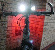
FoggyLogSun Oct 23rd 2005 17:22:16: LED Bike LightsHaving got fed up with weedy bike lights which continually require fresh batteries, I decided to build my own. My final design consisted of two 5W White Lumiled LED's and one 1W Lumiled Red LED and they really are very bright (suitable for riding at high speed through a forest, as I have proved!). Power comes from a 12V 4Ah Lead Acid battery - complete over kill (it will last about 2 hours between charges) and heavy, however it was cheap and is easy to charge (I can float charge it over night and not have to worry about over charging it). For the front LED's I used an elliptical lens and a narrow lens, which gives me a good short range beam and a long range beam. The lenses are designed for use with the LED's (Farnell 489-4376 & 489-4492). The main challenge was the circuitry to run the LED's, as they require a constant current. Here is my solution: 5W White Lumiled driver circuitThe circuit I used came from Zetex Application note 44. This uses a ZXSC300 driver chip. The schematic was as follows:
The 5W LED's are able to handle an maximum average current of 700mA with a maximum peak of 1A. I think this circuit stuffs slightly less current than that through the LED. 1W Red Lumiled Driver CircuitThe circuit for the lower power LED was the same as above, but with the following parts list (changes highlighted):
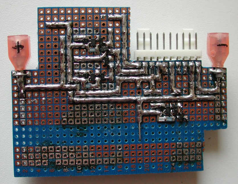
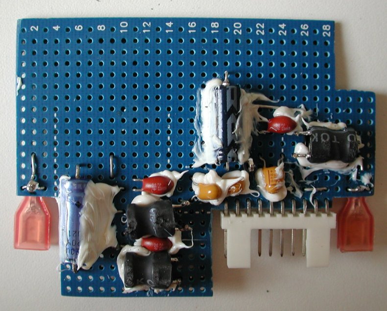
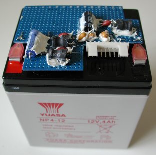
ConstructionThe soldering was "challenging" as there were a lot of surface mount components and I was making it on pad board. Here's what it looked like when I'd finished. The silicon gunk around the through hole components is to stop them vibrating around and breaking their legs.
The seemingly strange shape of the pad board should be explained when you see how I mounted the board....
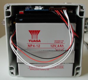
Which then fitted into the box like this:
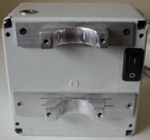
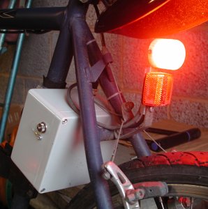
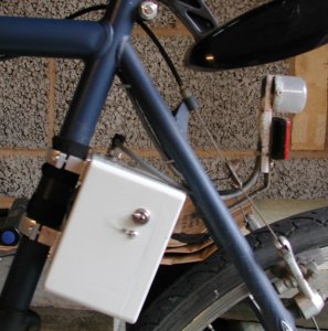
There is a 5 way connector on the top which connects the electronics to the LED's and a 2 way connector on the side for charging the battery. The switch is down the side of the battery (which is where the white wires are headed for). The battery box is attached to my bike using some brackets I hand crafted out of aluminium and tamperproof torx bolts. The rear red LED is attached to a lump of aluminium which is mounted on the bike's red reflector bracket. It is kept water proof by a translucent plastic pot that I chopped the top off. As you can see 1W of red light is a bit like a fog light - that should get me noticed on the roads....
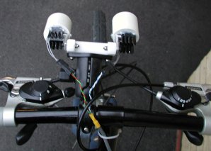
The front LED's are mounted on a RAM mount which allows me to quickly remove them when I'm leaving the bike unattended. (It also allows me to mount my GPS on my bike in place of the lights, as I have a RAM mount for that as well :-). They are kept water proof by the Lumiled lens combined with a bit of white plastic plumbers pipe!
The 5W LEDs get quite warm if there is no air flow (i.e. you are stationary), so I used a little heat sink which I attached to the lump of aluminium that the LED's are mounted on.

|
|